Mode management in the Requirements and Systems Portal
Every system has its different operating modes. For example, a mobile phone has gaming mode, power saver mode, etc. On each of these modes, the subblocks of the mobile phone (Processor, GPU, Screen, etc.) have their own operating modes.
Modelists are used when a particular property is not a single value but depends on the operation mode of a certain product, equipment, or unit. Power consumption is a good example of this, as it often depends on the operating mode.
Modelists are essentially schemas for arrays (Matrix Valis in our case) which can be used to harness the power of Valitypes and Requirements and Systems Portal’s automatic calculation propagation features by linking varying multiple modelists (schemas) down a block tree.
For instance, the system’s overall power consumption depends on the mode that the system is in. In the mode “ON” all Blocks and sub-blocks of the system will be switched on, in “STANDBY” some of the system's blocks will be running whilst others may not be. In “OFF” all blocks will be switched off.
The total power consumption of an Quadcoper will depend on the mode in which the system is operating [OFF, STANDBY, TAKEOFF, CRUISE, LANDING: the parent mode] and within each mode how do different sub-blocks behave (subsystem mode).
Let’s understand this with an example.
Parent mode: in Figure Valicopter Modelists, for the Valicopter, “Passengers” (number of passengers) and the “Flight mode” are the parent mode that dictates the power consumption. As such we click on the block (1), navigate to its “Modelists” tab and add a Modelist which will serve as a schema for our mode dependent Valis.
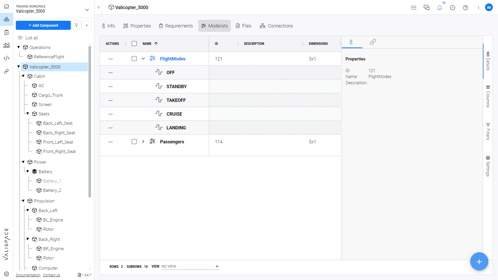
Valicopter Modelists
Similarly in Figure Propulsion Modelists for the Propulsion sub-system (1), there are four parent modes (2): OFF, MANOEUVER, CRUISE, STANDBY (3).
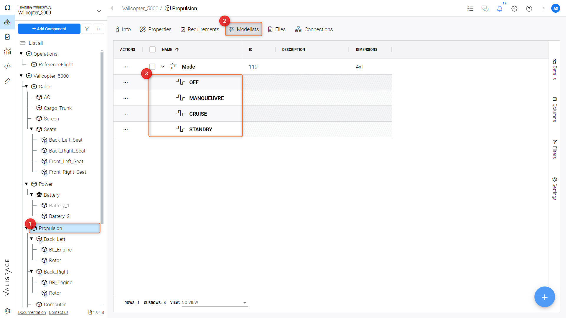
Propulsion Modelists
Subsystem mode: subsystem modes are the modes that are assigned to the sub-blocks of the main Block. Let’s take the example of Propulsion.
The parent modes as defined above for Propulsion are OFF, MANOEUVER, CRUISE, and STANDBY.
In Figure Sub-Block Modelists, the subsystem modes (2) of its subblock “Back_Left” (1) are OFF, ON, POWER, and HOLD (3).
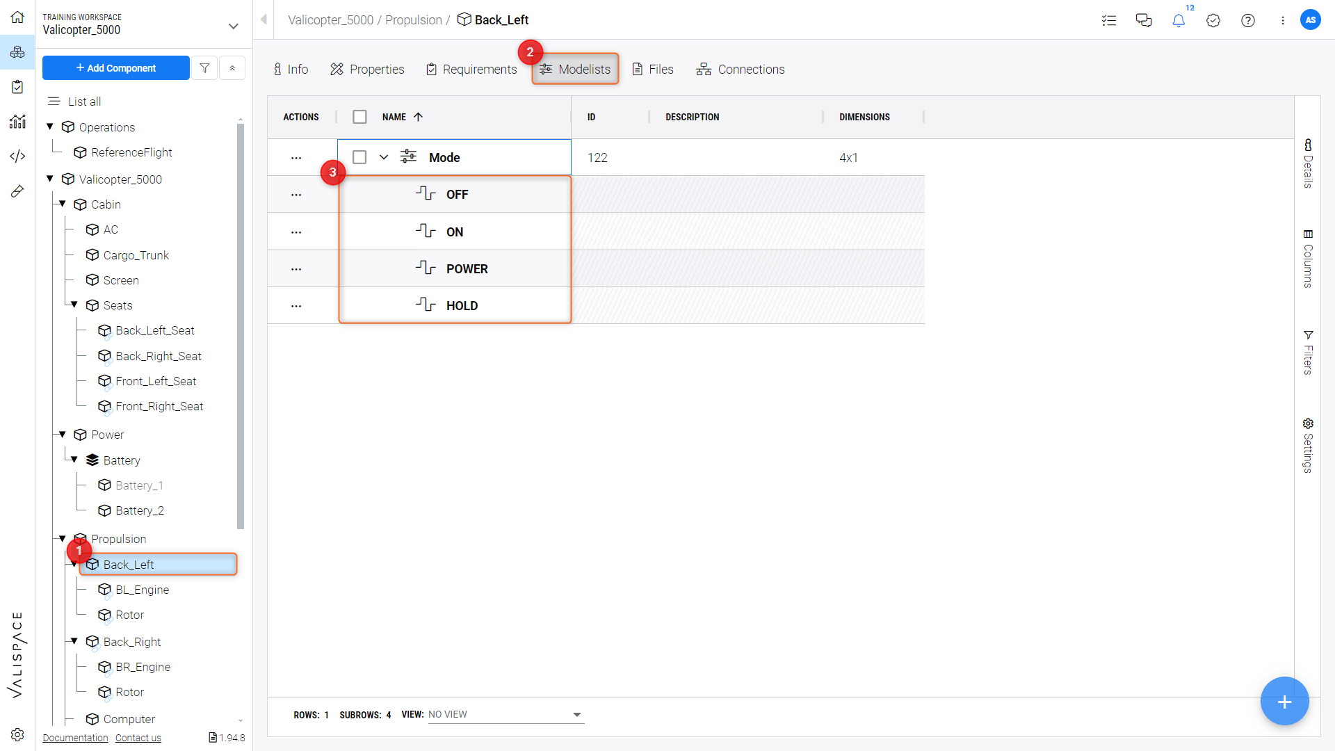
Sub-block Modelists
Assigning values to the modes of the sub-blocks
Once we have set up the modes for the individual blocks we can then create (1) a matrix (2) of Valitype “PowerConsumption” that is mode dependent as specified in the “Mode Reference” field (3) as in Figure Creating a Mode Dependent Matrix ,
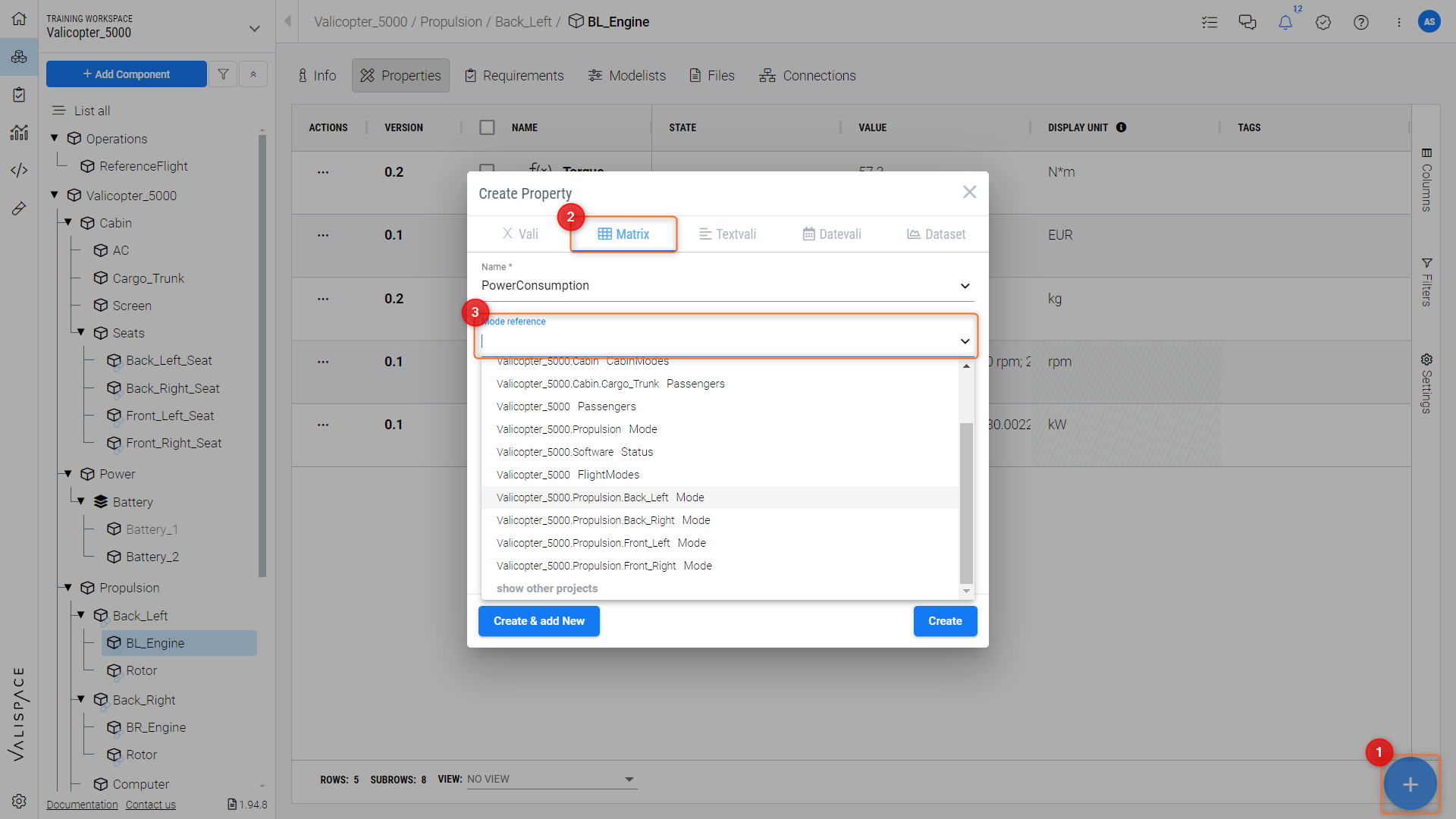
Creating a Mode Dependent Matrix
or convert a standard Vali into a mode dependent Vali (Figure Converting a Vali into Modelist Dependency) by clicking “Mode dependent” (1) in the Vali’s “info” panel and selecting the applicable Modelist (2).
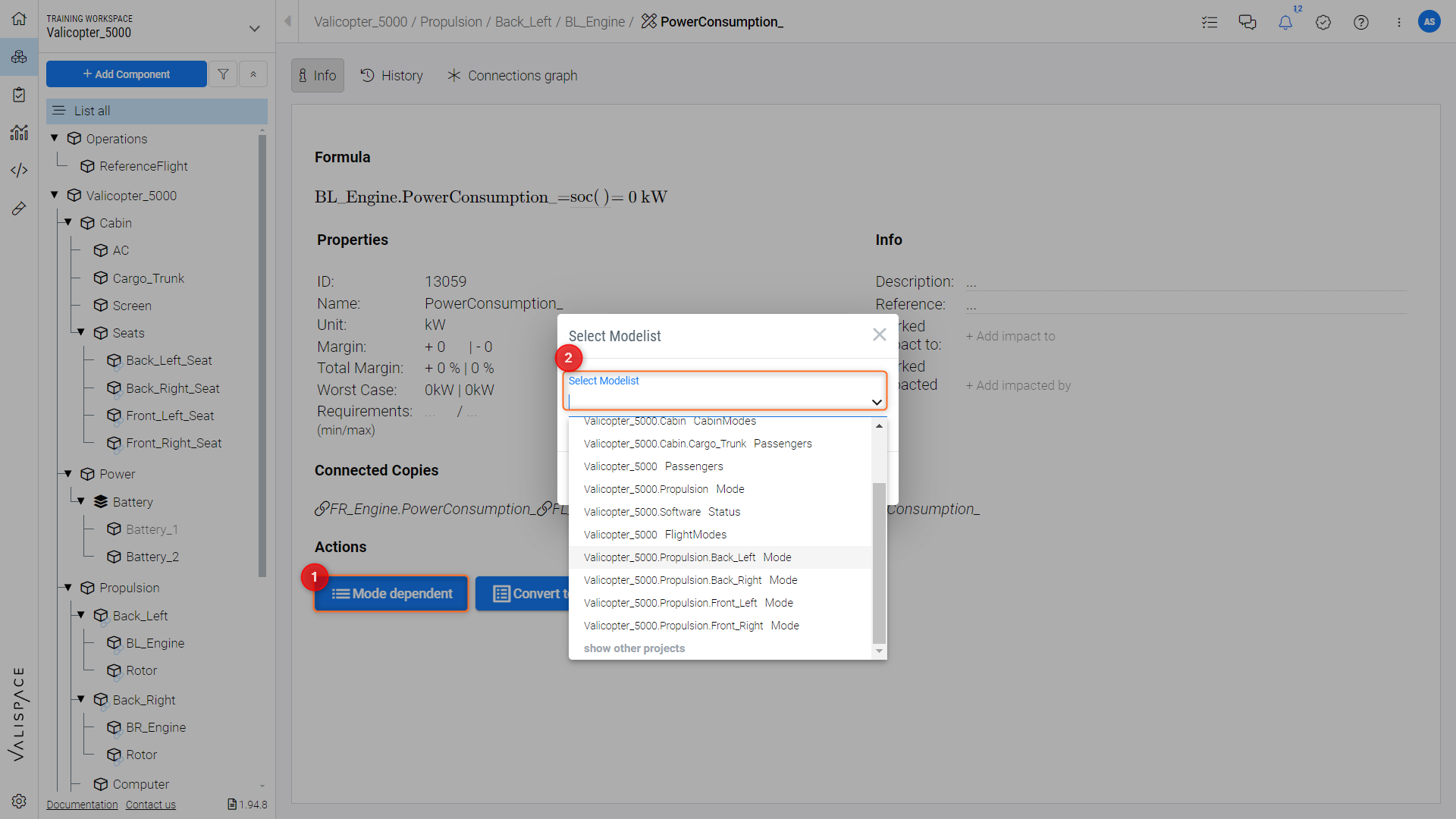
Converting a Vali into Modelist Dependency
Here we can specify the value of the power that is consumed in that particular mode.
In Figure Mode-Dependent Vali, we can see the defined power consumption formulas and calculated values (2) of the back left engine (1) in each of the previously specified modes.

Mode-Dependent Vali
Now that we have defined the modes and power consumption values of the sub-blocks we can now define the top-level system modes for example Flight Modes [OFF, STANDBY, TAKEOFF, CRUISE, LANDING], and then determine the overall power consumption of the system. This is achieved by linking the modes of the sub-blocks to the top-level Valicopter modes.
Linking Modes
The Video Linking Modelists shows the top-level system modes and the corresponding linked sub-block modes in the “Linked Modes” table.
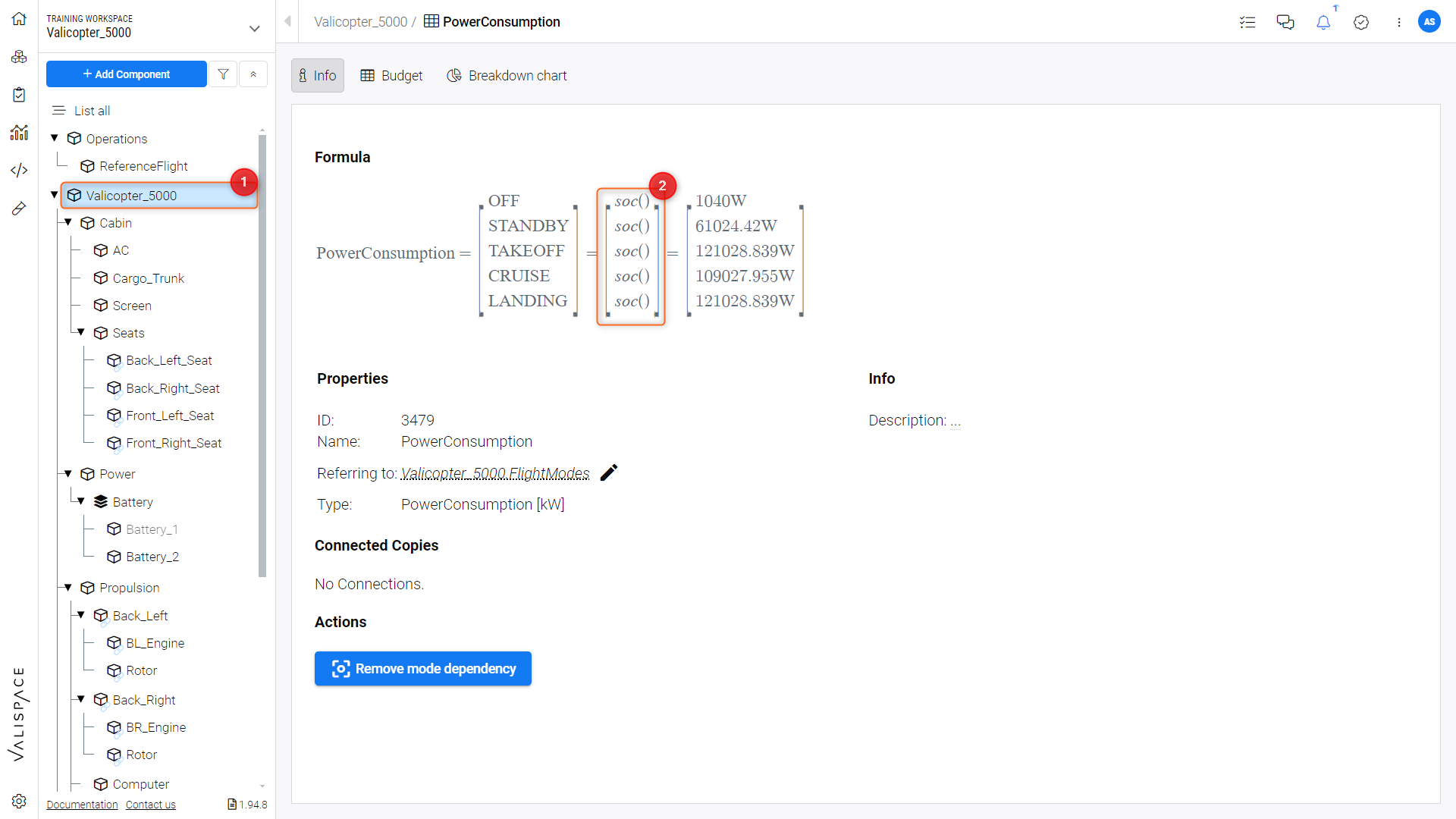
To calculate the system's overall power consumption, as in Figure Mode Dependent Vali-Type we can create a top-level “Valicopter_5000” block “Power Consumption” matrix (1). Requirements and Systems Portal will automatically calculate the overall power consumption for all the defined modes with the built-in “soc()” (Sum of Children) formula (2), which sums up all the power consumptions of the sub-blocks in the respective modelist links.
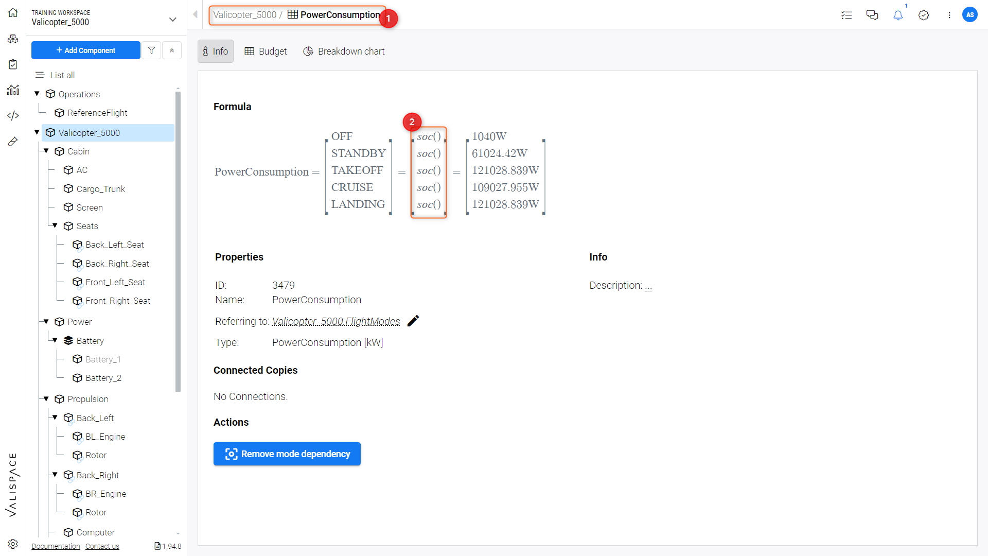
Mode Dependent Vali-Type
Linking from the top level to lower levels
In the Requirements and Systems Portal, we always link from a top-level Block. In this case, we linked the Valicopter to a low-level block, e.g., cabin, seats, power, battery, etc. The link works in one direction from sub-systems to top-level blocks.
In Figure block Based System Architecture, if you link from “Valicopter_5000” (1) -> “Propulsion” (2) and then “Propulsion” (2) -> “Back_Left” (3), the values will propagate up and sum in the top-level Valicopter.

block-Based System Architecture
Skipping a level when linking
When we link modes we can also link directly from a top-level (parent) to a low-level (grandchild) and skip intermediate levels. This can be done when the intermediate level does not have a “PowerConsumption” Vali.
For example, referring to Figure block Based System Architecture, we can define the power consumption of one of the four engines (“Back_Left” (3) which can be considered as the grandchild) in the propulsion system of the “Valicopter_5000” (Parent) (1) and link the modes here to the overall Valicopter system modes, without defining and linking the power consumption and modes in the Propulsion system (Child) (2).
Using the same matrix from the top level
We can also sum up Valis within matrices by linking matrices in blocks and sub-blocks to the same mode in the top level.
For instance, the overall power consumption can be summed up from the current of all the sub-blocks by the flight modes.
We can do this by first creating the “Flight_Modes” within the top-level system in Valicopter as in Figure “FlightModes” Modelist.
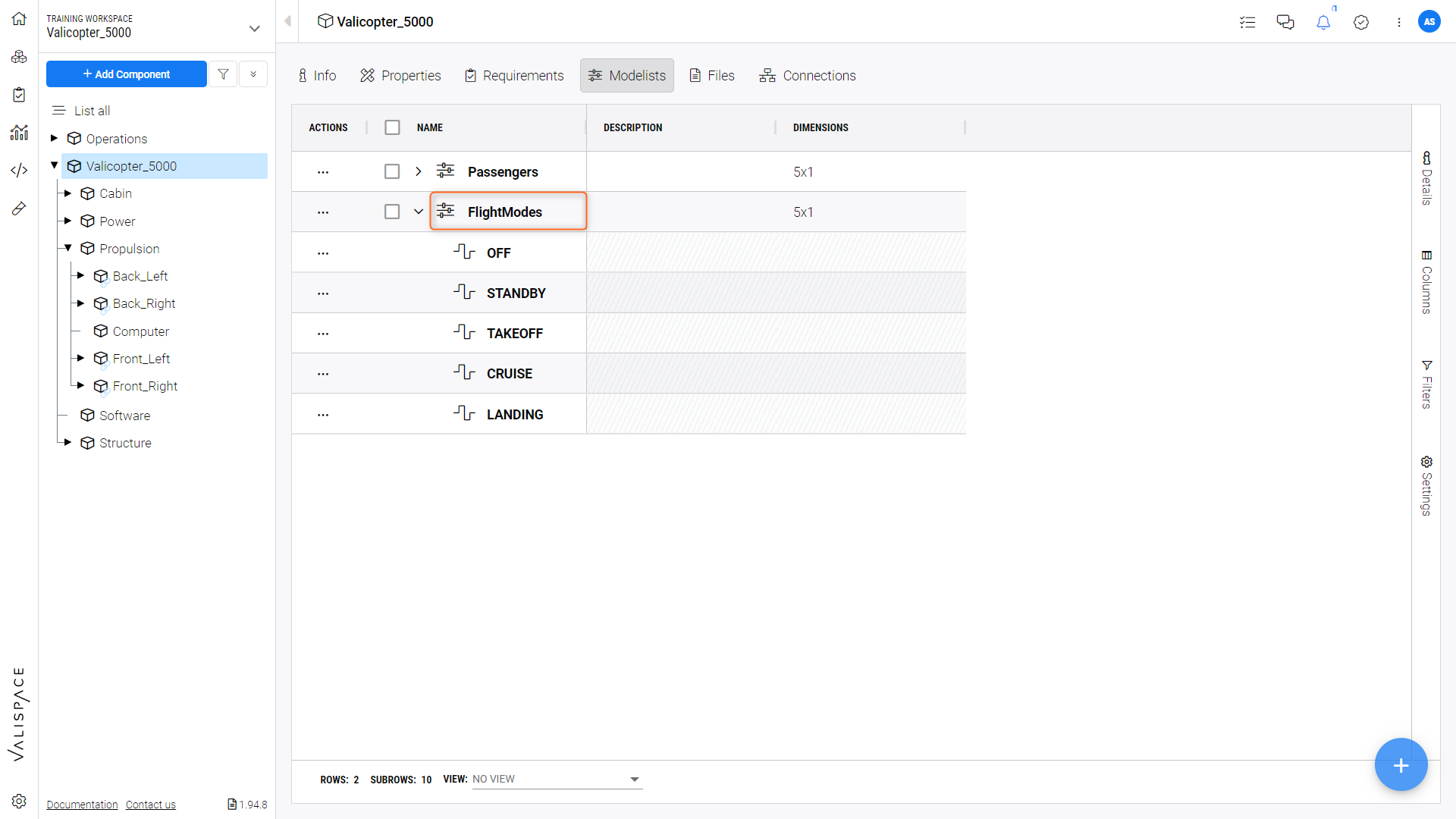
“FlightModes” Modelist
We then create the matrices “PowerConsumption” within the individual sub-blocks i.e “Cabin” (1), link them to the “Flight_modes” matrices within the Valicopter Enter the corresponding values of current within the “PowerConsumption” (2) matrix, as in Figure Inputing Cabin PowerConsumption Values.
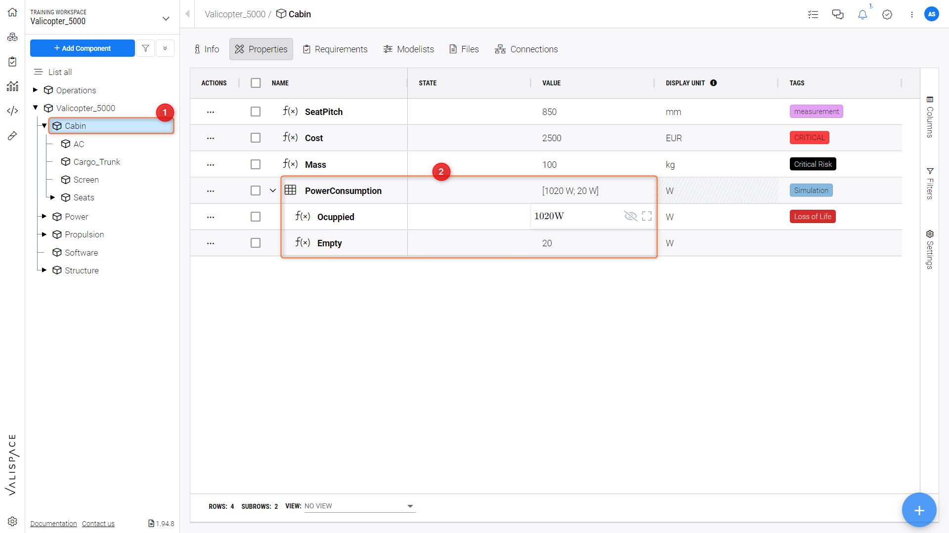
Inputing Cabin PowerConsumption Values
Then, we can create the “PowerConsumption” matrix at the top-level “Valicopter_5000” Block (1) with the “soc()” function as the value for each of its modes (2). This will sum up all the values from the now mapped sub-block modes within the matrix, as in Figure Adding Linked Modes.
Adding Linked Modes
Summing up a standard Vali with a Mode-dependent Vali
If you have a block within your system that has a Vali Type that is not mode dependent, you can add top-level block’s mode(s) by explicitely adding it to the .
For example, in Figure Standard Vali Type the Sub-block “Screen” in the “Valicopter_5000” sub-tree (1) has a non-mode dependent “PowerConsumption” Vali (2).
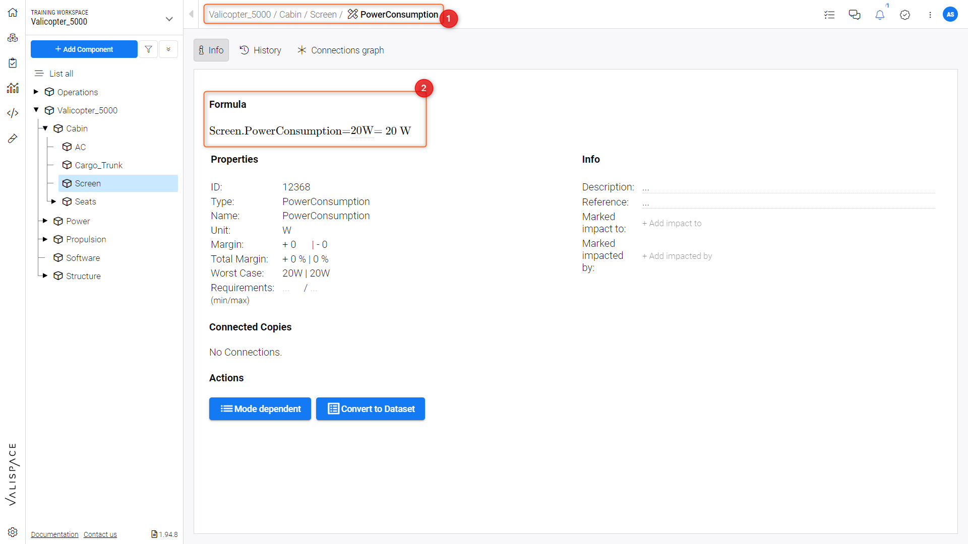
Standard Vali Type
This normal non-mode dependent Vali can be added to any of the modes (“[OFF, STANDBY, TAKEOFF, CRUISE, LANDING]”) in the mode dependant “PowerConsumption” matrix in the top-level “Valicopter_5000” block by explicitly referencing it in their respective formulas, as seen in Figure Explicit Mode Calculation and Video Mode Vali Dependency.
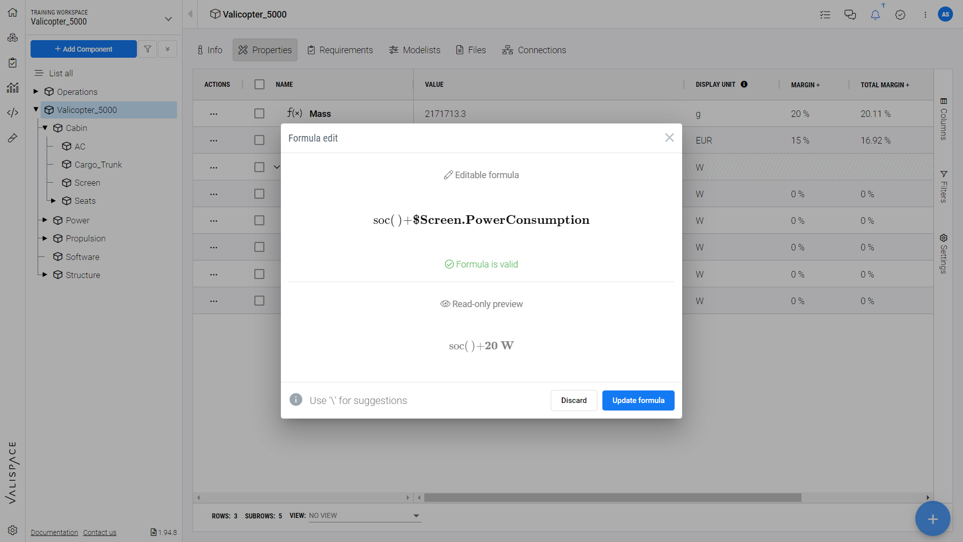
Explicit Mode Calculation.
Mode Vali Dependency