Fan Tutorial 2 - Design System - Part 2
In the context of this documentation “Valispace“ will be called “Requirements and Systems Portal“.
This part of the tutorial is expected to take around 10-15 minutes to finish.
(7) Tags for your Custom Needs
Tags are a multi-purpose tool for your specific team needs. You can use them to mark Valis and Blocks. Use them to indicate:
reliability of a value (assumption/calculated/measured)
actions for team members (review: Tom/approval: Christine)
any other marking or grouping
Tag the Mass of the motor as a measured value
Select the
MotorBlock in the product tree.In the row of the
Mass, double click into the cell of theTagscolumn, typemeasurement, and hit Enter to add the tag to the Motor.
If you want to search and filter for this tag, select the three horizontal lines which become visible when you hover over the header and select the filter option as shown in Figure Filtering.
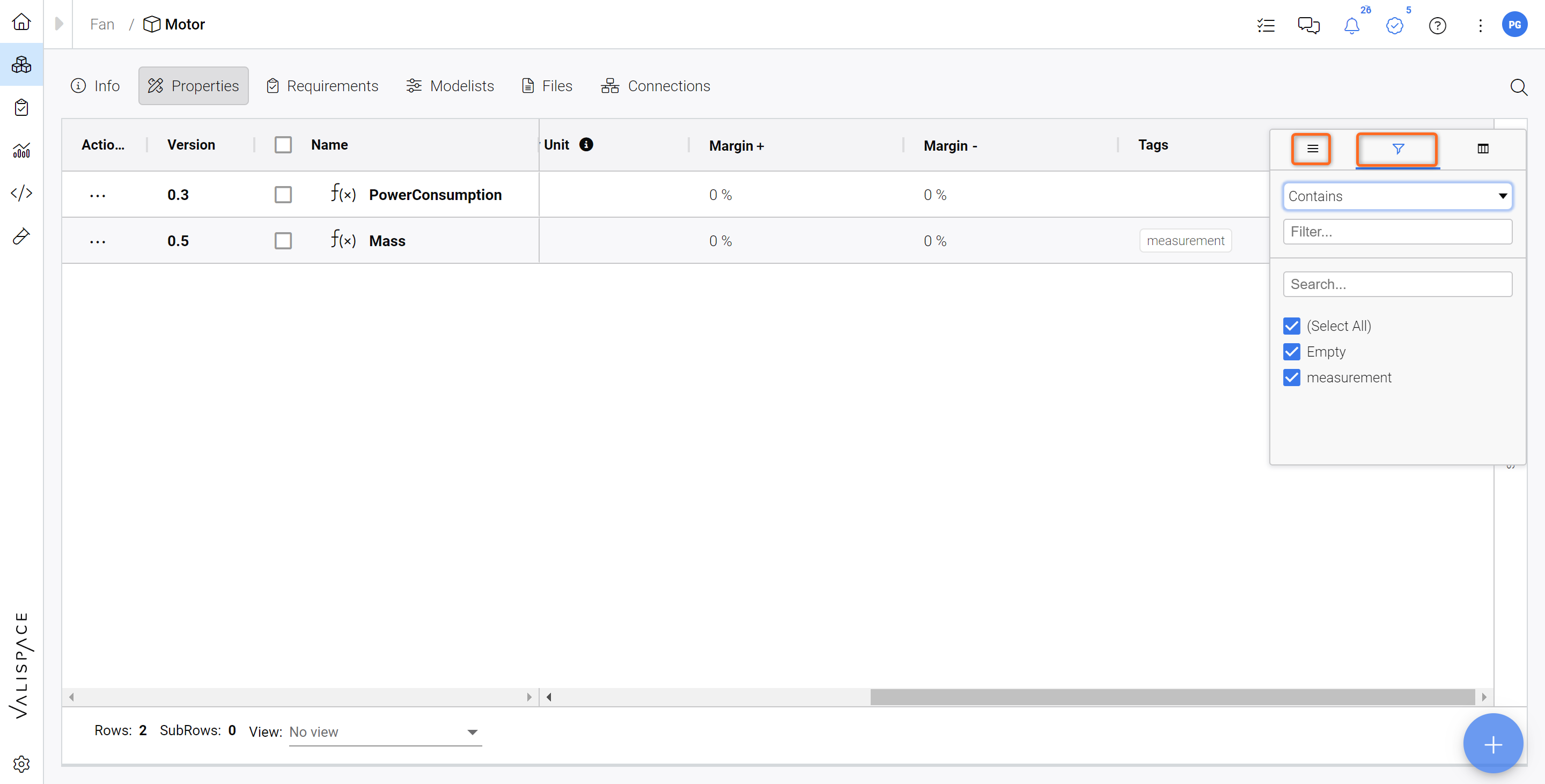
Filtering - You can apply filters on any column. In this example, we can Filter for tags.
PowerUserTip: if you want to change the colour of the tags, click on your Profile --> Settings and choose a new colour.
(8) Linking Block(s) to Requirements
Now that you have your basic System structure, let's establish a connection between the Fan system and the Requirements from our Fan_Specs Specification. This creates a direct link between the System Design and the Requirement.
To do this, go to the Requirements Module and access your Fan_Specs specification (1). Then select all the Requirements (2) and double-click into the “Applicable Block” Column (3). In the dropdown menu, select the Fan system (4).
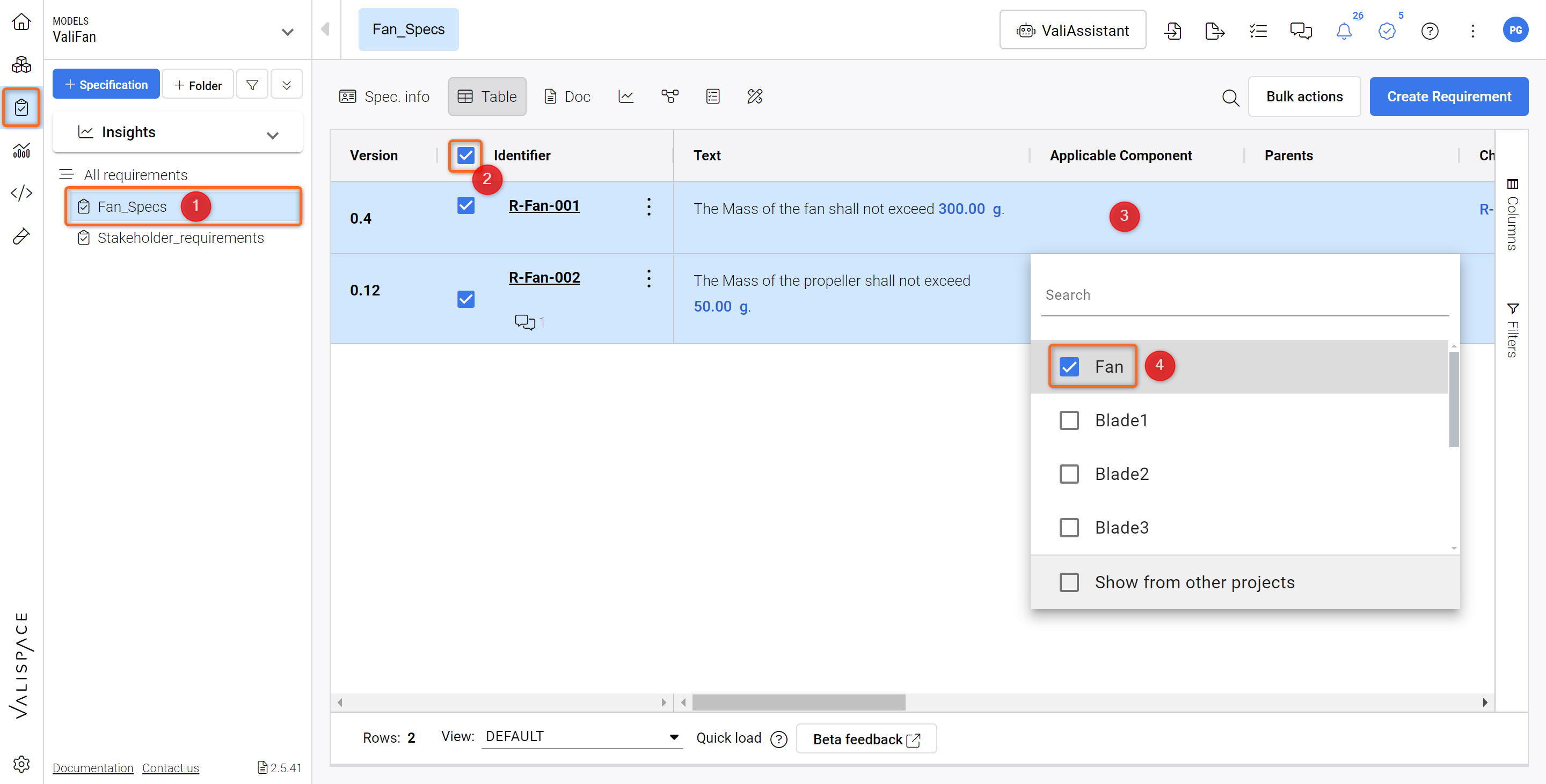
Setting up an Applicable Block - This creates a direct link between the Requirement and the Fan System
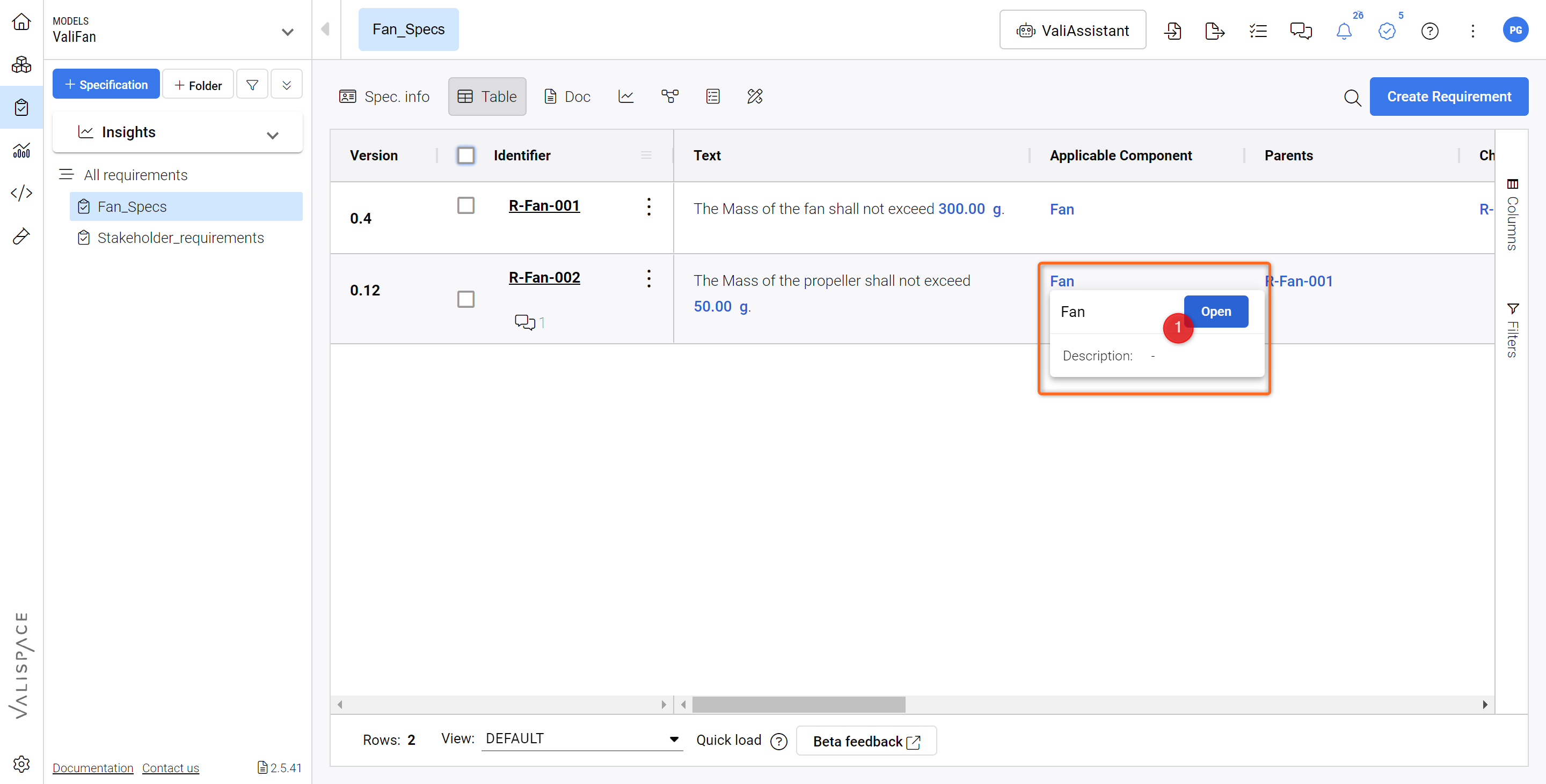
Now, you can click on “Open“ when hovering over the “Fan“ system in the “Applicable Block” column to access it in your System Design Module.
Navigate to the System Design Module through the link.
You can check the Requirements linked to this system by clicking on the “Requirements“ tab above the Vali table.

Accessing Requirements from the System side - here all Requirements are shown that apply to the selected system (in this case the Fan).
Whenever you create a Requirement here it will be automatically linked to the currently selected System.
For further insights on the Applicable Blocks feature, please check out our documentation.
(9) Creating Budget Tables and Pie chart
We now have a preliminary design breakdown of our system, and we would like to see the mass budgets in our Analysis document Project_Summary which was created in the previous tutorial (Specify Product - Part 2). Let's go ahead and add new blocks to our documentation.
Mass Budget Table
To create the mass budget table in our analysis document,
Select
Analysis Moduleand select theProject_SummaryScroll down and click
Click to add new blockSelect the option
Tableson the popup dialog box. Here, chooseBudget.A new block is added to the document. Click on the
Add data to this table. This opens a new dialog box where the user can select the valis they want to see the breakdown.In the
+ Add to vali, selectFan.Massandclose. This creates the budget table for our fan, which can be expanded as shown in the tutorial below.
Creating a Mass budget table in the Analysis Module.
Pie Chart for mass breakdown
To create a graphical representation of the mass breakdown, we can choose charts instead of tables.
Scroll down and click
Click to add new blockSelect the option
Charts(1) on the popup dialog box. Here, chooseBudget(2).
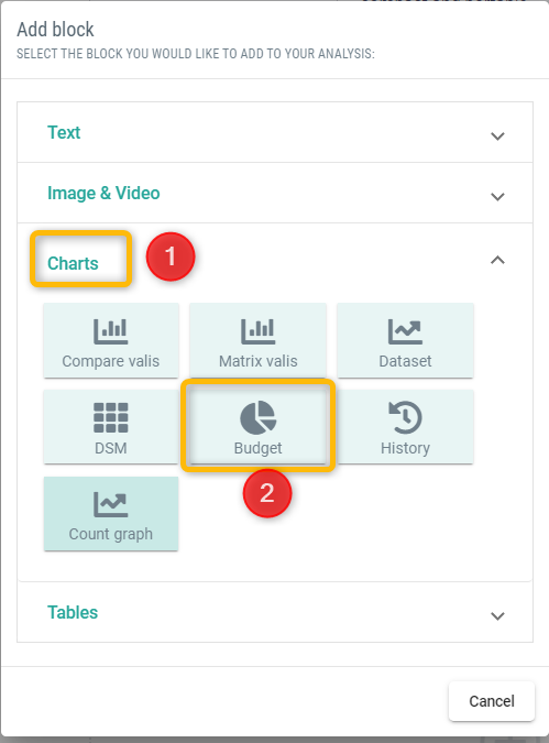
Selecting charts and creating a pie chart for the mass breakdown.
A new block is added to the document. Click on the
Add data to this table. This opens a new dialog box where the user can select the chart type and valis which they would like to see the breakdown for.In the
+ Add to vali, selectFan.Massandclose.
Before moving on with the next part of the Tutorial please check, which type of Verification Flow is active in your Requirements and Systems Portal! There are two ways of verifying Requirements in the Requirements and Systems Portal, through Verification and Validation (V&V) Activities and through Verification Methods (VMs). The V&V Activity flow will become the default one, whereas the VMs flow will be deprecated over the next months.
To check which one is active, please hover over the little test tube icon in your Module sidebar on the left:

If what you see looks like this ![]() , your admin has enabled the Verifications & Validations Module. Please continue with the Fan Tutorial 3a - Verify System - V&V Module.
, your admin has enabled the Verifications & Validations Module. Please continue with the Fan Tutorial 3a - Verify System - V&V Module.
If what you see looks like this ![]() , your admin has enabled the Test Module. Please continue with the Fan Tutorial 3b - Verify System - Test Module.
, your admin has enabled the Test Module. Please continue with the Fan Tutorial 3b - Verify System - Test Module.
Both Modules provide similar features but with a different look.