Fan Tutorial 3b - Verify System - Test Module
In the context of this documentation “Valispace“ will be called “Requirements and Systems Portal“.
Before moving on with this part of the Tutorial please check, which type of Verification Flow is active in your Requirements and Systems Portal! There are two ways of verifying Requirements, through Verification and Validation (V&V) Activities and through Verification Methods (VMs). The V&V Activity flow will become the default one, whereas the VMs flow will be deprecated over the next months.
To check which one is active, please hover over the little test tube icon in your Module sidebar on the left:

If what you see looks like this ![]() , your admin has enabled the Verifications & Validations Module. Please continue with the Fan Tutorial 3a - Verify SystemFan Tutorial 3a - Verify System - V&V Module.
, your admin has enabled the Verifications & Validations Module. Please continue with the Fan Tutorial 3a - Verify SystemFan Tutorial 3a - Verify System - V&V Module.
If what you see looks like this ![]() , your admin has enabled the Test Module. Please continue with the Fan Tutorial 3b - Verify System - Test Module.
, your admin has enabled the Test Module. Please continue with the Fan Tutorial 3b - Verify System - Test Module.
Both Modules provide similar features but with a different look.
This tutorial will discuss how to perform Verification and Validation using the Requirements and Systems Portal. We created requirements and Blocks for our ValiFan project in our previous tutorials. This tutorial will explain how verification methods are added to the Requirements, how they are verified using the closeout references, and also demonstrate the automatic verification methods in the Requirements and Systems Portal.
This part of the tutorial takes approximately 30 - 45 mins to complete. All the values and the requirements provided are arbitrary.
Before we begin, let's review the basics of verifications in the Requirements and Systems Portal. Requirements are connected to one or more Systems, or Subsystems. These Blocks are verified using verification methods. A Block's requirements can be verified with single or multiple methods. The Requirements and Systems Portal offers five default verification methods: Rules, Inspection, Analysis, Review, and Test.
We will explore how to add Blocks and verification methods to requirements and verify them with each verification method.
(1) Adding Default Blocks to a Specification
Let's add the Fan Block as default to our specification Fan_Specs. To add a default Block to the specification:
Select the
Fan_Specs(1) and the click on the Tab saying “Spec- info“ (2), which brings you to the Fan_specs details tab (see Figure Specification Info)
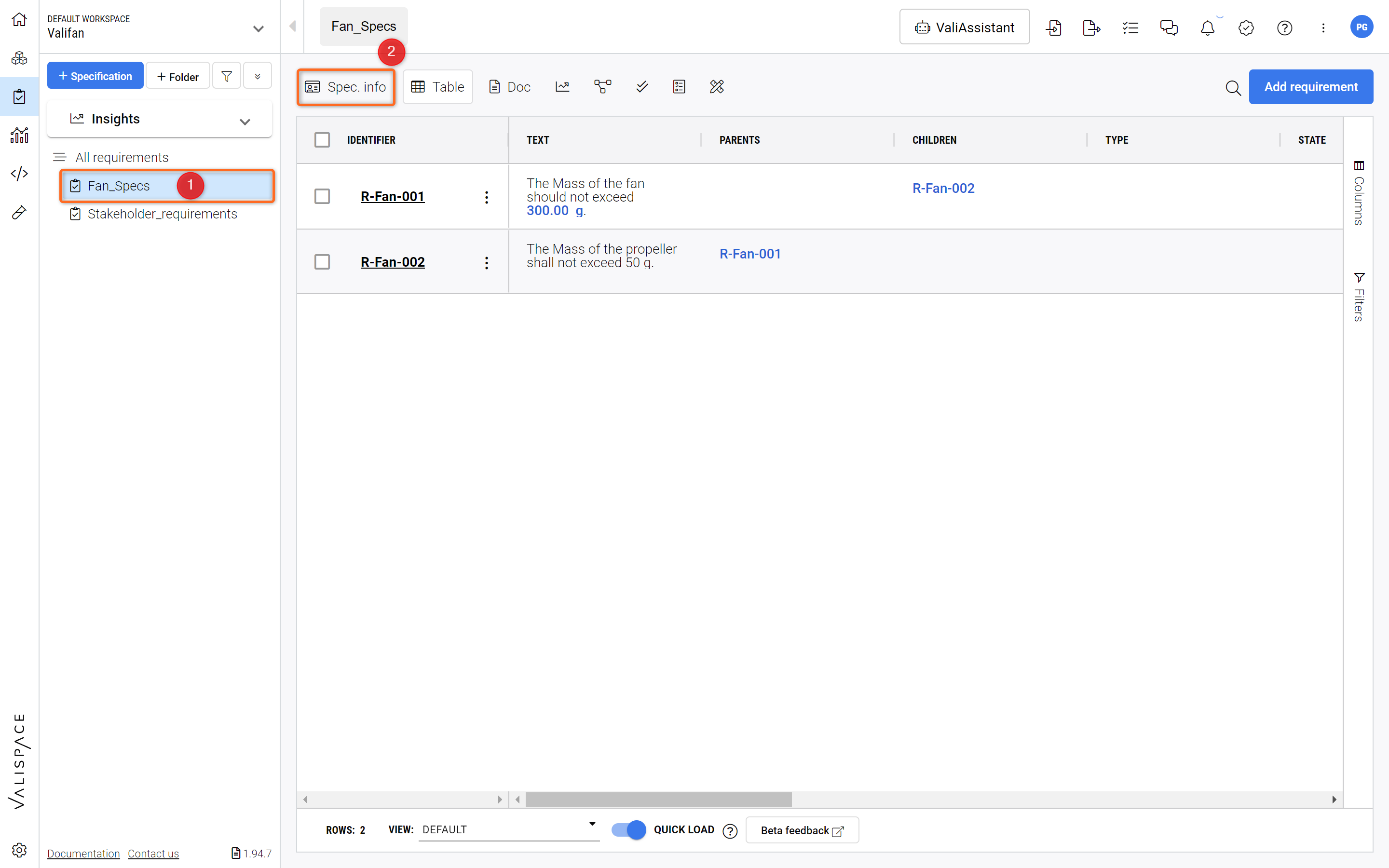
Accessing Specification Info - By clicking on “Spec. info“ you reach the information tab of the Specification.
In the Specification info tab, click on "Default Blocks" and in the dropdown select “Fan“ to add it to your Specification as a default Block (see Figure Default Specification Block).
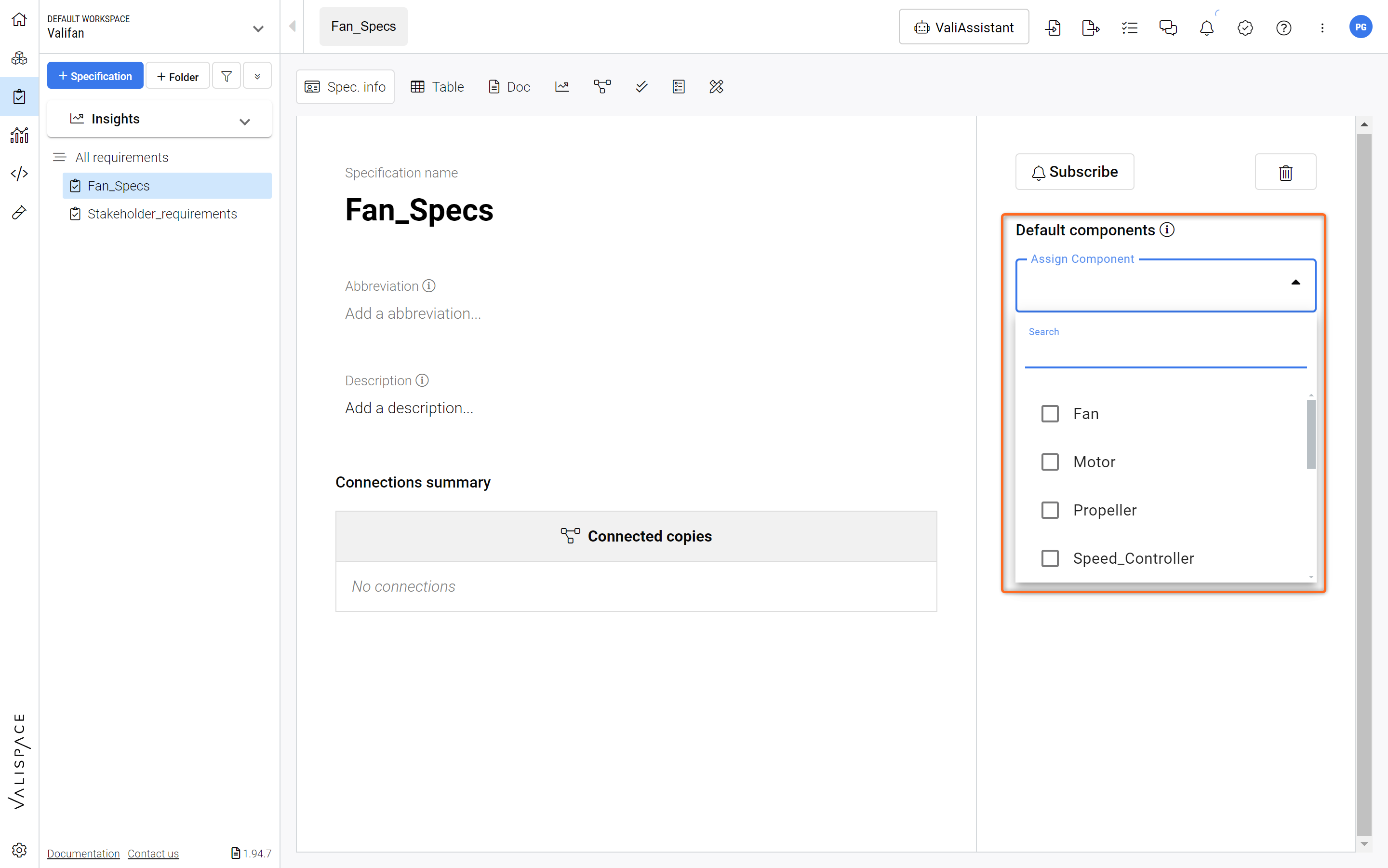
Default Specification Block - Adding default Blocks to your Specification makes it easier to carry out the Verification.
After selecting the “Fan“ as your Default Block you will be asked: “Do you want to add Blocks to existing requirements?”(1) in a pop-up box. Select the option “Yes, I’m sure“(2).
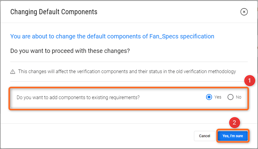
Adding Default Blocks to Specification - Selecting this option automatically adds the Blocks to the Requirement’s Verification Methods.
Like this we have now assigned the Block “Fan” to all the requirements in the “Fan_specs” specification. In case you have already defined a verification method, the Block is automatically assigned to the verification method.
(2) Creating and Loading Views for Verification
The Requirements and Systems Portal offers various pre-selected attributes, such as Identifier, Text, Parents, Children, Type, State, Verification Status, Verification Methods, Blocks, Closeout References, Tags, and Properties. However, this may lead to excessive horizontal scrolling on smaller screens. To streamline the Verification process, users can generate custom views with only the essential attributes. Let's create a new view for the Verification and load it.
Hover over any one of the attribute name cells. A new icon shows, as shown in the image below. Click on the icon to open the menu.
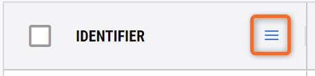
Accessing additional information for a column.
Once you click on the icon, you have a new dialog box, Select the last icon with three vertical windows.
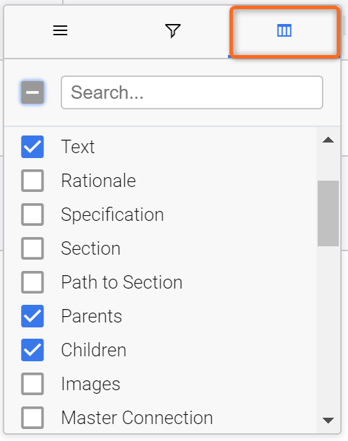
Selecting Columns to be displayed in the Table.
In this box, unselect all the attributes and select only the following attributes: Text, Parents, Children, Applicable Blocks, Verification status, Verification Methods, Closeout references and Tags.
The user can also select/unselect the attributes through the “Columns” on the right side. We have shown this approach to make you also aware of the additional options you have on the column headers, such as Filters and table sizing options. For instance, the funnel symbol provides filtering options for a specific column.
Upon finishing, right-click on the tables to open the tables menu. In the dialog box, select
Save View.
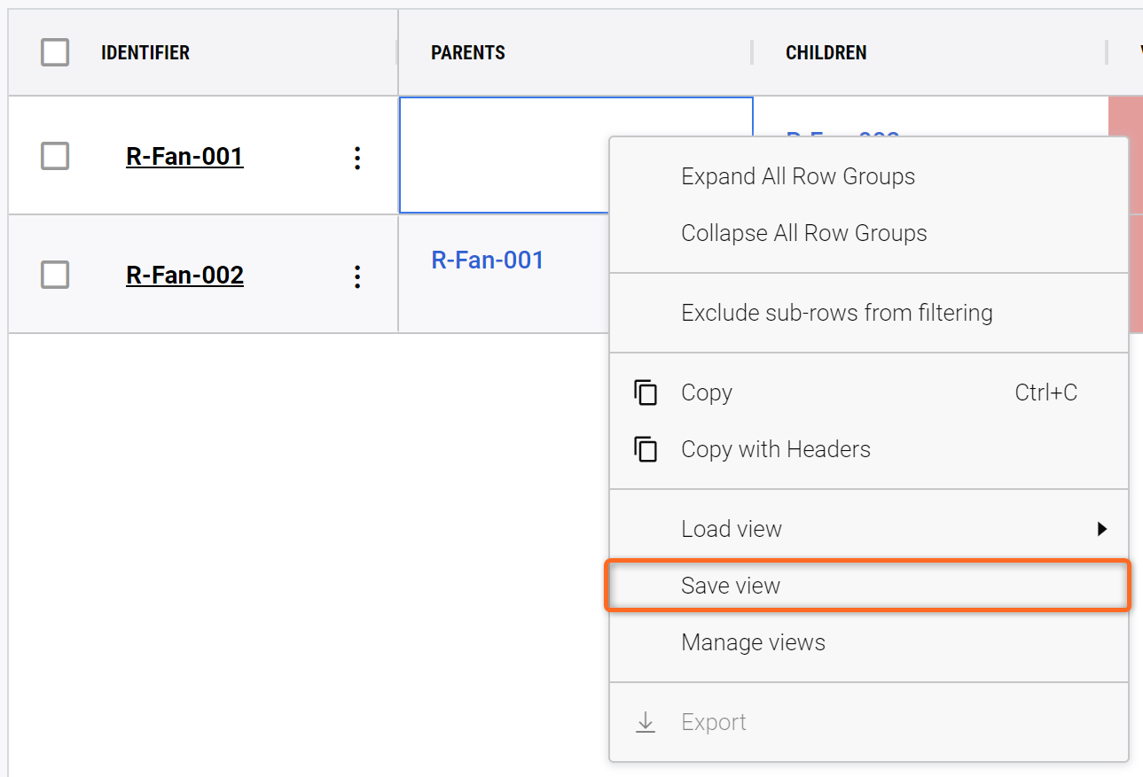
Save View - By saving a View all selected columns, column widths and applied Filters will be saved in a dedicated View.
A new dialog box opens where you can input “Verification_View” in
Save as new(1), selectPrivate(2), and then clickSave(3).
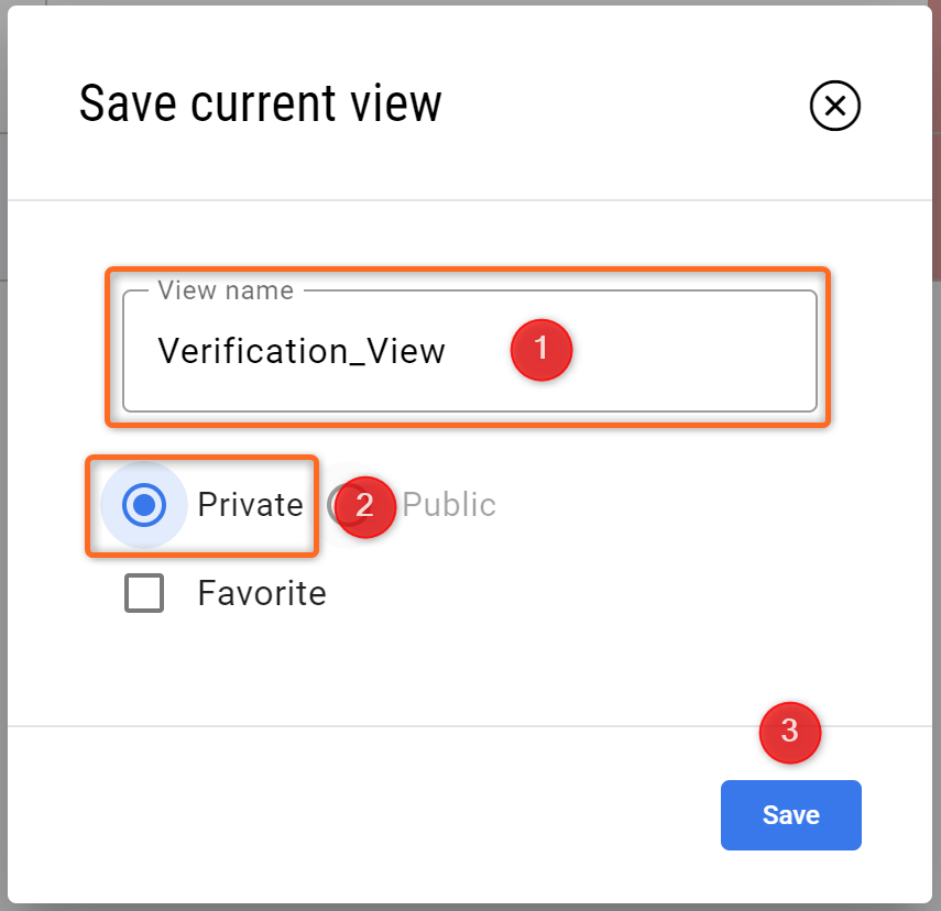
Saving a View - Here, you can select the name of your view as well as if it is private (just you can see it) or public (all your collaborators can see it) and you can select whether it is a favorite View.
Once the view is saved, the user can now load them by right-clicking on the tables, selecting the option
Load Viewand selecting theVerification_Views.
(3) Adding a Verification Method to Requirements
The Requirements and Systems Portal has five default Verification Methods: Rules, Inspection, Analysis, Review and Test. Inspection, Analysis and Review are manual verification methods, while the Rules and Tests are automatically updated based on the triggers in the System Design Module and Test Module. We will create each Verification Method and show you how to attach the Closeout References.
Closeout references: Supporting information that proves the verification method.
Manual Verification Method
Let’s add a manual verification method to the requirement R-Fan-001. To do that,
Click on the three dots icon on the
Actionscolumns of the requirement and selectAdd Verification Method.A new dialogue box opens, where you can select the Verification method. For the manual verification method, we will select
Inspectionand clickYeson the confirmation window.Please check the Tutorial below for the flow.
Adding a verification method to a requirement
What happens when we add a Verification Method?
Once we assign a verification method to a requirement, it is added below. You can check this by clicking the
>symbol near the Identifier nameR-Fan-001. Clicking on the>symbol expands the Verification method row (see Figure Requirement Verification Method).
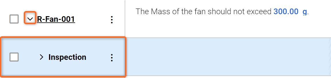
Requirement Verification Method - The Verification Method is displayed in a dropdown below the Requirement.
Note: the > icon near the inspection method is shown. When the > is selected, the Block row expands where it shows the attached Verification method. Since we have added “Fan” as a default Block, it gets automatically assigned to the Verification methods.
The red colour on the Block shows that the Verification method is not verified, while green indicates it as verified.
The user can add multiple Blocks to the verification method by selecting the three dots on the Verification Method and selecting “Add Block“.
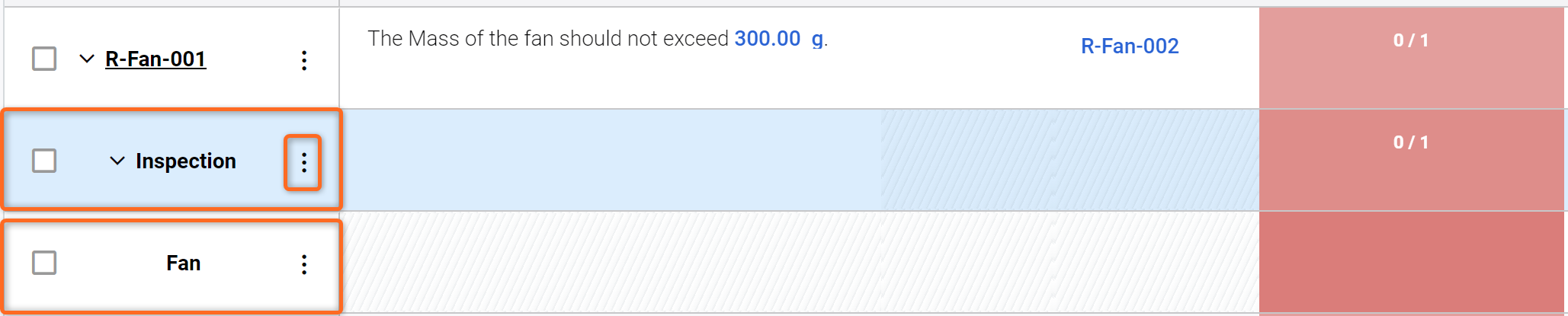
Verification on a Requirement - Requirement with Verification Method and Block attached.
Changing Verification Status
To update a Block's verification status, follow these simple steps. First, ensure that the Block meets our standards through a thorough inspection. Once you have confirmed that it aligns with our requirement, double-click on the red box in the Verification Status column of the Block and select "verified" from the drop-down menu (1) (see Figure Changing Verification Status).
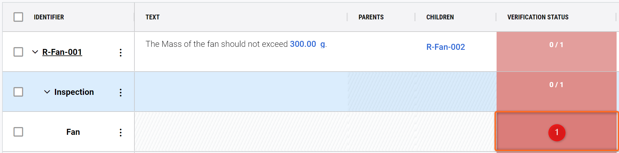
Changing Verification Status - Double-clicking on the red box opens a dropdown menu, which allows you to select the current verification status.
The Block's row colour will change from red to green, indicating that it has been verified. To confirm that the update has been successfully implemented, check the numbers - it should now indicate “1/1”.
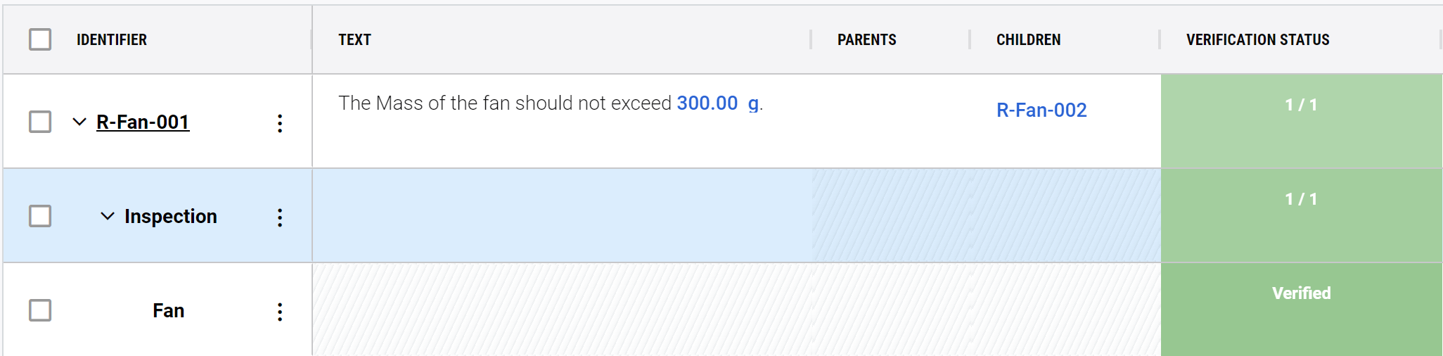
Requirement Verified - When the Verification Status is changed to “Verified“, the colour changes, giving you a clear indication that the Block satisfies your Requirement.
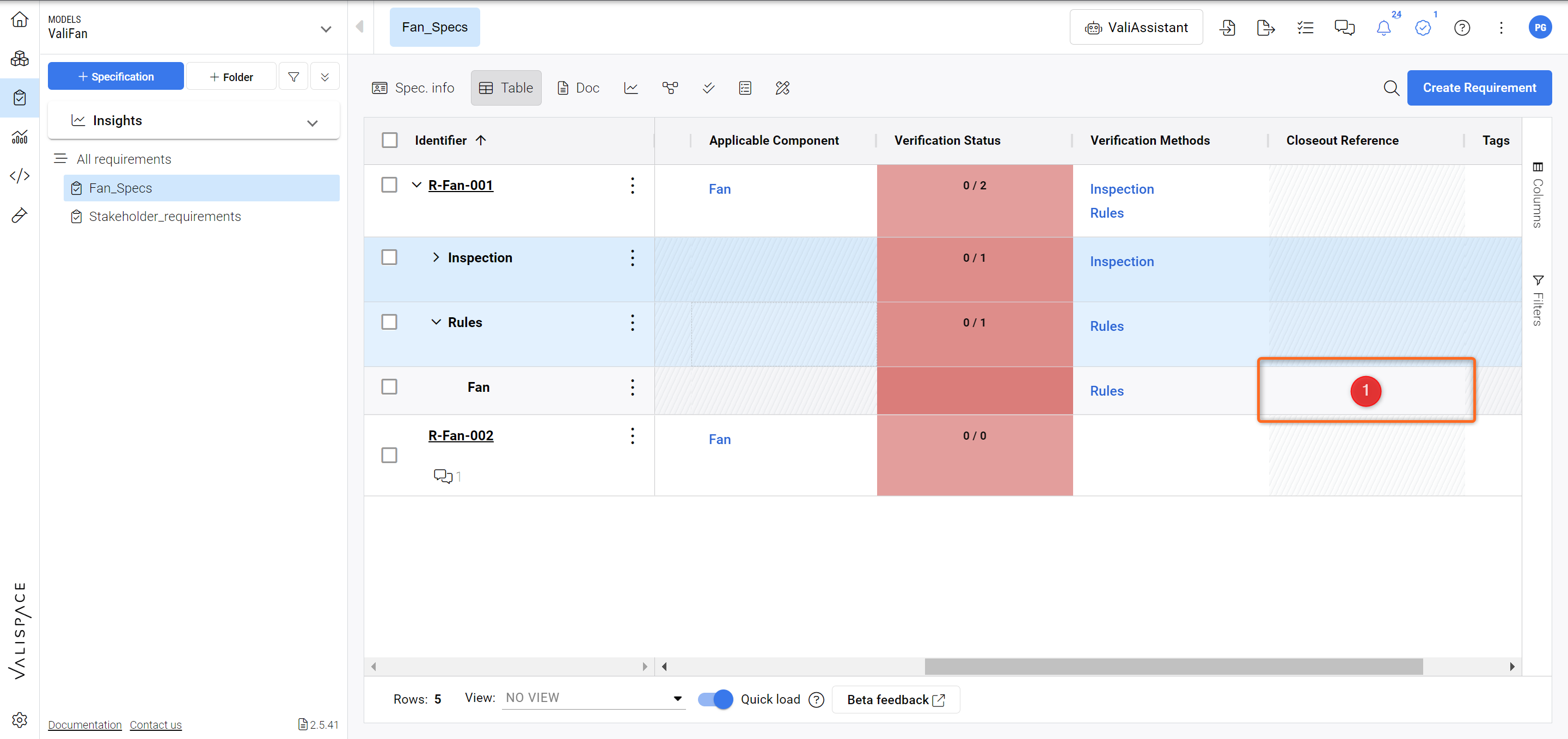
For the Analysis Verification method, the procedure is similar, however, the “Closeout Reference” column is used to upload an external document or Report from the Analysis Module within the Requirements and Systems Portal and then manually changing the verification status if the document proves the verification.
Automatic Verification Method
Rules - Verification method - Track your Valis against Requirements
Most technical developments are designed against strict requirements, e.g., mass, power consumption, budget, etc. The Requirements and Systems Portal maintains a complete overview of whether your design fulfils all of these requirements.
In the row of
R-Fan-001, click on the three dots icon near the identifier and select the first option,Add Verification Method. In the pop-up “Add New Verification Method”, select “Rules” and click on “Yes”.Click on the small arrow button near R-Fan-001 and again on the one next to Rules to open the Fan Block in the next row.
Double-click into the cell in the closeout reference column (1) to get a pop-up to add your rules (see image below Adding a Rule).
Adding a Rule - Adding a Closeout Reference to a Rule Verification Method.
In the pop-up type the following rule
$Fan.Mass <= 300g(1). Click on “Done” (2) - see Figure Rule Verification Method
ProTip: Instead of the fixed 300g, search for the Vali (by using the dollar sign “$”) that was created in the Text of the Requirement and compare it to the Mass of the Fan from the system design module.
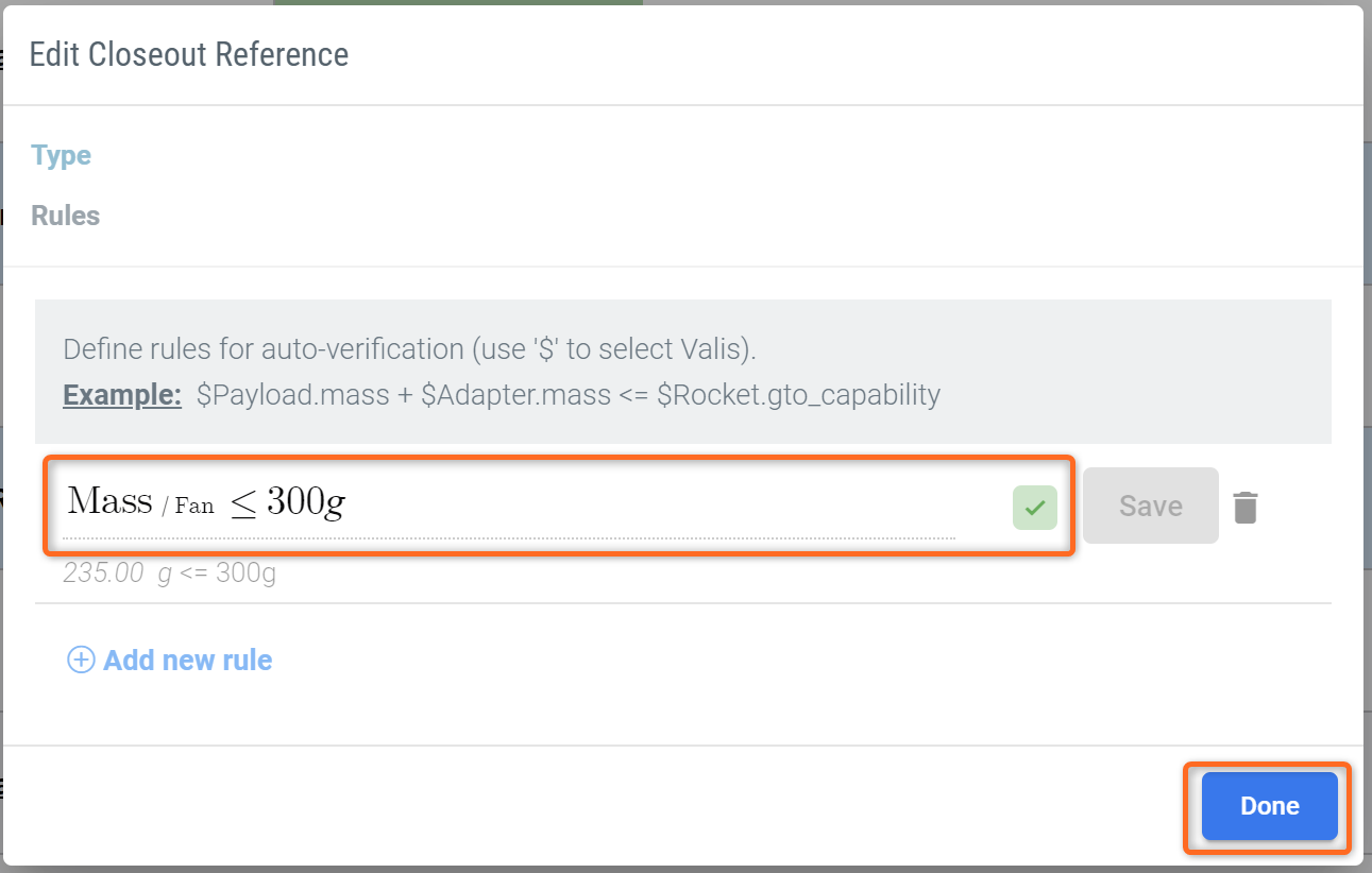
Rule Verification Method - By adding various Rules to your Requirements, you can perform automatic Verification against your System Design.
The Requirements and Systems Portal automatically checks for verification of this rule. The green on the requirement 2/2 notification indicates that this requirement has been met and verified by two verification methods. Please use our click-through tutorial below to follow along:
You can also always check the status of all requirements and rules of the project by opening the
Verification Statustab in theRequirementsModule.
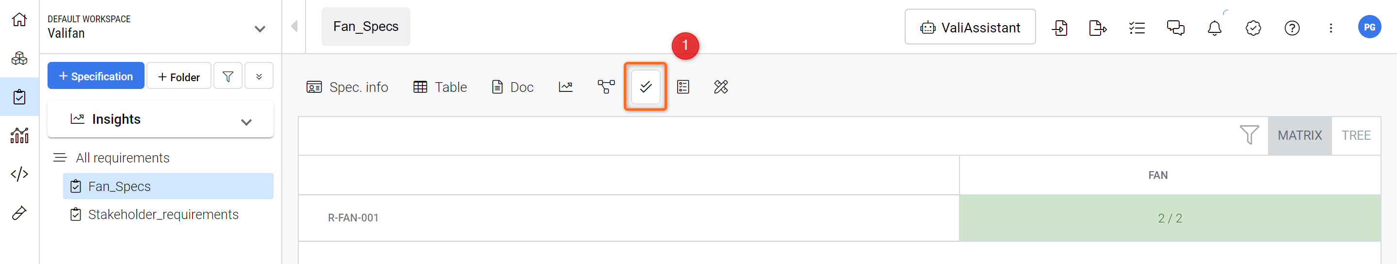
Verification Status Tab - Shows the overall Verification Status of your Requirements in the selected Specification.
PowerUserTip: The tracking of the requirements also takes defined margins into account. In case your worst-case value calculated with margins violates the requirements, the tool will let you know if you use the property function i.e. property($<search_for_vali>, worstcase_plus). You can refer to our documentation here.
Tests - Verification Method (Optional)
The test verification method works concurrently with the “Tests Module”. Within the “Tests Module”, the user can write the testing procedure and attach requirements and Blocks to it. During the testing phase of the Block, the testing engineer can perform the test runs and verify if the test is approved or not. Based on the test run results, the verification status of the requirements gets updated automatically.
Create a new test procedure.
In this section, we will create a brief test procedure, perform a test, and observe the verification process. To accomplish this, we will:
Select the Tests module(1) and when the module screen shows, click on
+ Test Procedure(2)
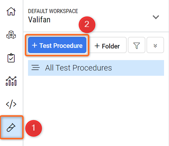
Test Module - Access and Creating a Test Procedure.
A dialog box opens where the user can input the Name of the test procedure as
Mass_measurement_of_ValiFanand clickCreate.After creating the test procedure, On the right side, the user can define the details of the test procedure and write the steps. In the details section, find the
Units under testand add the BlockFanto the test procedure.
Creating a new test procedure and adding “Units under test”
Now, let's create the test steps, expected results and the requirement
Click on the "+" located on the bottom right side to add test steps. This will open a new dialogue box where you can add
Preparing the Equipmentto the Title section. In the text box, input the following text:
Place the precision balance on a stable and level surface.
Turn on the precision balance and allow it to stabilize.
Calibrate the precision balance based on the manufacturer's guidelines.
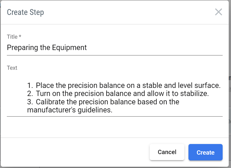
Adding a Test Step
Similarly, add the following step with the following details.
Title | Text |
|---|---|
Determine the mass of the fan. |
|
Now, add the expected result to step 1 and step 2.
Double click on the cell of “Expected Result” on the row of step 1 and add the following text “The balance should show 0.0g
Do the same for the second step with the following info: “The mass should be less than 300g”.
The second step of this test procedure can verify the requirement R-Fan-001. So, let's add the requirement to the second step.
Hover to the cell of the “Requirements” column of step 2. Click on
+ Add requirement.Upon clicking, a new dialogue opens. In the drop-down type or choose
R-Fan-001andSave.
After saving the test step to the requirement, a new verification method will be created on the requirement. The test step will also be added as a closeout reference to the Block. This means that if the testing engineer performs test runs and they are approved, the requirements will be automatically updated based on the test results. The video below demonstrates all these steps, but it is not part of the tutorial. If you are interested in trying it out, please follow the video.
Test run and automatic propagation of test run status to requirements
Verification Assignment Matrix
The requirements Module has a feature named "Verification Assignment Matrix". This feature allows the user to view a matrix that shows which Verification Methods are assigned to each requirement. Additionally, users can easily add or remove verification methods within this matrix. To do so, follow the steps provided.
Within the Requirement Module, select the section
Verification Assignment Matrix(1)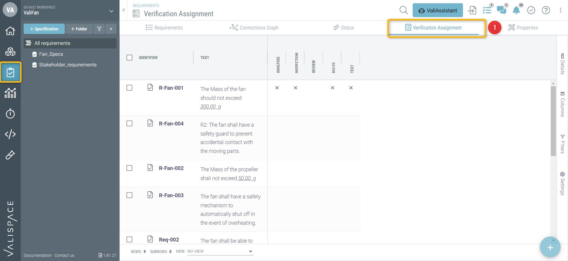
On the cell that coincides with the “rules” Verification Matrix and the requirement
R-Fan-002,click on the cell. This automatically creates the rules verification method on the requirement.Similarly, you can click on the other cells and quickly add Verification Method.
Next Steps?
Congratulations, you now know your way around the Requirements and Systems Portal!
You can continue improving your Desktop Fan project. Here are some ideas:
Add Compliance to your requirements
Add a few parent/children relationships between requirements, check the Connections Graph, and notice the colour codes on the requirement.
Right-click on the Requirement Table and the Export options.